Imagine building a four-legged robot that can walk around, respond to wireless commands, stream camera footage, and execute programmed movements without needing a Raspberry Pi as its main controller. Sounds like an expensive laboratory experiment? Not necessarily. The TNY-360 is an open-source quadruped robot project designed to make hands-on robotics more accessible to electronics enthusiasts, students, engineers, and makers.
Developed by the TNY Robotics team, the TNY-360 combines an ESP32-S3 microcontroller, servo-driven legs, sensor feedback, custom circuit boards, and 3D-printable mechanical parts in a compact robotic platform. Its open-source design gives builders access to firmware, CAD models, PCB files, and a bill of materials, allowing them to study how the machine works instead of treating it as a sealed commercial product. The official project repository also describes a dual-core architecture that separates time-sensitive movement control from communication and user-interface tasks. Source: TNY-360 GitHub repository.
For anyone interested in embedded systems, automation, artificial intelligence, or DIY robot projects, this is an exciting opportunity to explore how mechanical engineering and software come together. You can begin by understanding the hardware, then progress toward custom walking patterns, remote control, sensor-based behaviors, and more advanced experiments.
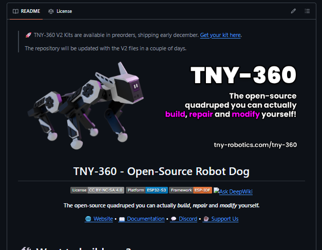
1. What Is the TNY-360 Robot Dog?
The TNY-360 is an open-source, four-legged robot designed to be built, programmed, repaired, and modified by its community. Unlike a simple wheeled robot that moves using two or four motors, a quadruped must coordinate several joints to lift its feet, support its body, and move without losing stability. That makes the project a useful introduction to the challenges involved in legged robotics.
At the heart of the platform is an ESP32-S3 development module. The robot combines this controller with multiple servo motors, a dedicated PWM driver, an inertial measurement unit, a camera, and other sensors. Its modular electronic architecture is designed to keep the wiring organized and make future modifications easier. Rather than relying entirely on a proprietary controller, builders can explore the firmware and hardware designs themselves.
The project is particularly interesting because its documentation covers more than just the finished robot. You can investigate the mechanical models, understand the electronic connections, study the control software, and follow the assembly process. This makes the TNY-360 useful as both a functioning robot and an educational platform.
It is important to understand what open-source means in this context. The project publishes substantial hardware and software resources, but builders still need to source components, manufacture or assemble the electronics, print the mechanical parts, and configure the firmware. The robot is not simply a downloadable program that makes any ESP32 board walk. It is a coordinated hardware-and-software system.
2. Why the ESP32-S3 Makes This Robot Special
The ESP32-S3 is a capable microcontroller with dual-core processing, wireless connectivity, and interfaces for communicating with external sensors and peripherals. It is commonly used in connected electronics, embedded control systems, and maker projects where developers need more processing capability than a basic microcontroller can provide.
In the TNY-360, the ESP32-S3 acts as the robot’s central controller. It coordinates motion-control software, communicates with peripheral electronics, and manages network interactions with external control interfaces. The official repository identifies the ESP32-S3 N16R8 module as the main processing platform.
One major advantage is that the robot does not require a Raspberry Pi to run its primary embedded control system. A microcontroller-based design can be compact and power-conscious, and it allows the robot to execute its motion-control firmware directly on the ESP32-S3. This is different from a typical robotics architecture in which a single-board computer runs high-level software while a separate microcontroller handles motor timing.
That does not mean a Raspberry Pi or computer would never be useful. External computers can still be valuable for advanced vision processing, simulation, data analysis, or robotics middleware. The key distinction is that the TNY-360’s core controller is designed around the ESP32-S3 rather than depending on a Raspberry Pi for its basic operation.
3. Dual-Core Processing and Real-Time Movement
One of the project’s most interesting engineering decisions is its division of processing tasks between the ESP32-S3’s two cores. According to the project repository, one core is dedicated to the time-sensitive motion-control loop, while the other manages tasks such as communication, the web interface, and higher-level orchestration.
The movement-control loop is described as operating at 200 Hz, equivalent to 200 updates per second. At that rate, each control cycle lasts approximately five milliseconds. This allows the controller to repeatedly calculate and update motion commands rather than relying on occasional, widely spaced adjustments.
Why does this matter? Imagine trying to balance a broom upright on your palm. You need to observe its movement and make small corrections before it falls too far. A robot faces a related challenge: its controller must process feedback and adjust joint commands quickly enough to produce stable, coordinated movement.
Separating time-sensitive work from network and interface tasks helps protect the control loop from unnecessary delays. Wireless communication can be unpredictable, and camera or interface activity may consume processing resources. A carefully designed software architecture helps prevent those tasks from interfering with critical motion updates.
However, a high update rate alone does not guarantee good walking performance. Stability also depends on sensor quality, actuator response, mechanical construction, control algorithms, calibration, and the robot’s center of mass. The TNY-360 is valuable because it offers an opportunity to explore these interacting engineering challenges in a practical project.
4. Key Features of the TNY-360
The TNY-360 combines several features that make it more advanced than a basic four-servo walking toy. Its open-source construction, modular electronics, feedback-based actuator design, and wireless interface create opportunities for experimentation at different levels of complexity.
| Feature | What it offers |
|---|---|
| ESP32-S3 controller | Runs the robot’s embedded control firmware |
| Twelve leg servos | Provide the main joints needed for quadruped movement |
| Position feedback | Supports closed-loop control when the specified servos are modified correctly |
| Dual-core architecture | Separates movement control from communication tasks |
| OV2640 camera | Provides a camera-based vision interface |
| Wi-Fi connectivity | Supports wireless control and communication |
| Bluetooth capability | Provides a wireless interface where supported by the hardware and firmware configuration |
| 3D-printable structure | Allows builders to manufacture and replace mechanical parts |
| Custom PCBs | Organize power distribution, control, and sensor connections |
| Open-source files | Enable inspection, modification, and learning |
The official project also lists an IMU for orientation measurements, a time-of-flight distance sensor, an OLED display, and audio hardware. These components create a foundation for experimenting with environmental awareness, user interaction, and more sophisticated robot behaviors.
Feature availability should be checked against the exact repository version you intend to build. Hardware revisions and firmware releases can change component choices, setup procedures, and software support. Start with the current official documentation rather than assuming every feature mentioned in a demonstration is available in every build.
5. Hardware Components You Need to Build It
Building the TNY-360 requires more than an ESP32 board and a collection of hobby servos. The robot depends on mechanical components, feedback-capable actuators, power electronics, sensors, wiring, and custom circuit boards working together.
The official repository provides a bill of materials that helps builders identify the required parts and their associated resources. The following table summarizes major components documented for the project.
| Component | Purpose |
|---|---|
| ESP32-S3 N16R8 module | Main embedded controller |
| 12 MG996R servos | Drive the primary leg joints |
| 2 SG-90 micro servos | Operate the head or ear mechanisms |
| PCA9685 PWM driver | Generates control signals for multiple servo channels |
| OV2640 camera | Supplies image data |
| VL53L0X time-of-flight sensor | Measures distance to nearby objects |
| MPU6050 IMU | Measures acceleration and angular motion |
| SH1106 OLED display | Displays status or simple visual information |
| INA219 sensor | Monitors voltage and current |
| Custom PCBs | Organize the robot’s electronic subsystems |
| Rechargeable battery system | Supplies power to the controller and actuators |
| 3D-printed frame | Provides the mechanical structure |
Source: Official TNY-360 repository. Confirm the exact bill of materials for your selected revision before purchasing parts.
Power deserves special attention. Servo motors can draw substantial current, particularly when multiple joints move at once or experience mechanical resistance. The battery, wiring, connectors, power-distribution boards, and voltage regulators must be appropriate for the real load. The ESP32-S3 should not be expected to power all the servos directly from its logic supply.
You should also follow the project’s specified battery configuration and protection requirements. Lithium-based battery packs need suitable charging, overcurrent protection, insulation, and secure mounting. Poor power design can cause resets, unstable motion, overheated wiring, or damage to electronic components.
6. Servos, Sensors, and Motion Control
The TNY-360 uses twelve MG996R servos for its main leg joints. Each leg has multiple joints, allowing the robot to change foot position and body posture. Coordinating these joints is more complicated than simply rotating each motor forward or backward because the movement of one joint affects the geometry of the entire leg.
A conventional hobby servo typically receives a position command but does not necessarily provide the external controller with a convenient measurement of its actual output position. The TNY-360 addresses this limitation through a modification that enables analog position feedback, using a custom operational-amplifier buffer circuit described in the project’s documentation.
That modification matters because a controller needs to distinguish between the position it requested and the position the actuator actually reached. Mechanical resistance, backlash, electrical noise, and actuator delays can all create differences between desired and measured movement. Feedback gives the control software additional information with which to manage these errors.
The PCA9685 PWM controller helps generate signals for the robot’s many servo channels. This reduces the burden of generating every servo-control signal directly through the ESP32-S3’s general-purpose pins. Meanwhile, the IMU provides measurements that can help the software understand the robot’s motion and orientation.
Combining these parts creates a useful embedded-control learning environment. You can investigate how actuator feedback is measured, how sensor readings are filtered, how joint positions are commanded, and how control algorithms respond when the robot’s body moves unexpectedly.
7. How the Robot Dog Walks and Maintains Balance
A quadruped robot needs a movement strategy that coordinates its four feet and maintains a stable relationship between its body and the ground. Walking requires each leg to alternate between supporting the body and moving toward its next foothold. The timing and positioning of these actions influence how smoothly the robot moves.
One important concept is inverse kinematics. In simple terms, inverse kinematics calculates the joint angles needed to place a robot’s foot at a particular position. Instead of commanding every servo independently and hoping the foot reaches the intended location, the controller uses the robot’s leg geometry to calculate coordinated joint targets.
Consider a robot that needs to move one foot forward. The control software first identifies the desired foot position, then calculates the joint angles needed to reach it. Those angles become servo targets. Feedback and motion-control routines can then help the robot approach those targets while managing mechanical limitations.
Balance adds another layer of complexity. The controller needs to consider which feet are touching the ground, how the body is moving, and whether the robot is likely to tip. An IMU can provide useful orientation and acceleration measurements, although sensor readings alone do not automatically create a complete balancing system.
The TNY-360’s documented closed-loop motion architecture makes it a particularly useful platform for exploring these concepts. Builders can study gait generation, joint limits, calibration, and feedback-based correction without needing to design every subsystem from scratch.
Keep expectations realistic, though. A four-legged robot does not automatically walk over every surface or recover from every fall. Performance depends on assembly accuracy, servo condition, calibration, battery state, the surface under its feet, and the capabilities of the control firmware.
8. Camera, Wi-Fi, and Wireless Communication
A robot becomes much more interesting when you can interact with it without connecting a USB cable every time you want to change its behavior. The TNY-360 combines wireless networking with a camera-based interface, giving developers a foundation for remote operation and experimentation.
The project lists an OV2640 camera module for vision. This sensor can supply image data for supported camera and streaming functions, allowing a remote operator to see what the robot’s camera captures. Actual resolution, frame rate, and streaming performance depend on the implementation, network conditions, and firmware configuration, so check the current documentation before assuming a specific video quality.
Wi-Fi provides the network connection used by the robot’s communication interface. The repository describes a WebSocket-based server, which supports bidirectional communication between the robot and compatible client software. This is useful because a client can send commands while receiving updates through the same general communication mechanism.
Bluetooth may also be useful for supported wireless interactions, depending on the firmware and configuration being used. Wi-Fi and Bluetooth serve different purposes, and neither should be assumed to provide identical range, bandwidth, or responsiveness.
The camera and wireless interface also open up educational opportunities. You could investigate remote teleoperation, create a custom control dashboard, record movement data, or experiment with basic computer-vision workflows on a connected computer. These are development possibilities rather than a guarantee that every AI vision function runs locally on the ESP32-S3.
9. 3D Printing the Robot’s Body
One of the biggest advantages of the TNY-360 is its 3D-printable mechanical design. Instead of manufacturing a complete chassis from metal or purchasing a proprietary replacement structure, builders can use the project’s CAD resources to print the specified components.
The repository includes CAD files and ready-to-print models. These resources can help you inspect how the robot’s body, legs, and mounting points fit together before you begin assembly. Depending on the supplied model and your needs, the editable CAD files may also provide a starting point for permitted modifications.
Material selection matters. PLA is convenient for prototyping and many indoor maker projects, but components around heavily loaded joints may experience repeated stress. Print orientation, wall thickness, infill, temperature, dimensional accuracy, and fastening methods all influence the final part’s strength. A part that looks correct on screen can still fail if its layer orientation or mounting geometry is unsuitable.
Before printing everything, inspect the assembly instructions and identify parts that require tight tolerances or heat-set inserts. A small test print can help verify fit before you commit hours of printing time. Make sure that motor mounts are secure and that moving joints do not rub against surrounding parts.
For makers with access to a desktop 3D printer, this project offers a practical way to connect digital design with physical engineering. You can learn about tolerances, mechanical loading, assembly order, and iterative prototyping while producing a functional robotic platform.
10. Custom PCBs and Open-Source Electronics
A robot with numerous motors and sensors can quickly become a confusing collection of wires. Custom printed circuit boards help organize connections, distribute power, and create a more modular electronic system. The TNY-360 repository includes PCB design resources alongside its firmware and CAD files.
The project’s modular architecture uses dedicated electronic boards and standardized connectors to organize the robot’s subsystems. This can make assembly and maintenance easier than wiring every component independently. If a board or connection needs troubleshooting, a documented layout gives you a clearer starting point for diagnosing the problem.
Open PCB files are also educational. You can inspect component placement, trace connections, review the bill of materials, and understand how signals travel between the controller and peripheral hardware. Experienced electronics enthusiasts may use these resources to study board design and learn how mechanical constraints influence electronics packaging.
If you intend to manufacture the boards yourself or order them from a PCB fabrication service, verify the correct revision first. Gerber files, component lists, pick-and-place data, and assembly instructions must match the intended hardware version. A mismatch can result in incorrect footprints, incompatible connectors, or a board that does not fit the printed chassis.
Open-source electronics provide flexibility, but they do not eliminate the need for careful testing. Check polarity, power rails, connector orientation, and continuity before applying power. Keep the motor supply within the specified limits, and avoid making wiring changes while the battery is connected.
11. Firmware, Python, and ROS 2 Integration
The firmware is the software layer that coordinates the robot’s hardware. It handles functions such as actuator control, sensor communication, movement updates, and network interactions. The TNY-360 repository includes ESP-IDF-based C/C++ firmware resources, making the project relevant to developers who want to understand embedded software beyond simple Arduino sketches.
Python offers another route for controlling the robot and creating higher-level behaviors. The project’s documentation describes a Python SDK that communicates with the robot through its API. This makes it possible to develop scripts on a connected computer without implementing every low-level hardware operation yourself.
For example, a Python script could send movement commands, organize a sequence of actions, or connect robot control to an external data-processing workflow. The exact commands and supported functions depend on the installed SDK version and API documentation.
ROS 2, or the Robot Operating System 2 framework, is widely used for robotics software integration. It provides communication mechanisms and tools that help developers connect sensors, control systems, visualization tools, and other software components. The TNY-360 documentation describes ROS 2 integration as under development, so check its current status before planning a project that depends on full ROS 2 compatibility.
The important distinction is that Python support does not mean Python runs the core motor-control loop on the ESP32-S3, and ROS 2 integration does not necessarily mean the full ROS 2 framework runs on the microcontroller. In this architecture, high-level software can communicate with the embedded controller through the documented interface.
12. How to Get Started With the TNY-360
The best way to begin is by treating the project as a complete engineering build rather than a quick weekend toy. Before ordering parts, read the official documentation, review the bill of materials, and identify which tools and electronic components you already own.
Start with the official repository:
GitHub: https://github.com/TNY-Robotics/TNY-360
The repository contains several important resource groups. The BOM directory helps identify required components, CAD contains mechanical design files, the PCB directories contain board resources, and Firmware holds the embedded software. Read the README and follow the current official assembly instructions because the project may evolve between releases.
You should also prepare a suitable 3D printer, the tools required for assembly, a computer for firmware development, and the appropriate USB and electronic connections. If the design requires modified servos, make sure you understand the procedure before purchasing all twelve units. The feedback modification is an important part of the control system rather than an optional cosmetic upgrade.
Plan your budget around the complete build. The total cost depends on component availability, the selected hardware revision, printing materials, PCB fabrication, shipping, tools, and whether you already have compatible equipment. Avoid assuming that the project is inexpensive simply because its source files are free.
Finally, give yourself time for calibration and troubleshooting. A robot can be mechanically assembled yet still need careful configuration before its first reliable movement. Starting with the official checklist can save considerable time.
13. Step-by-Step Robot Assembly
A sensible assembly process follows the dependencies between the mechanical structure, electronics, firmware, and calibration. The precise order should follow the current official guide, but the overall workflow can be understood through several stages.
Step 1: Review the documentation and bill of materials. Confirm the hardware revision and identify every required component. Check servo models, sensors, connectors, fasteners, battery requirements, and PCB versions before placing orders.
Step 2: Print and inspect the mechanical components. Use the supplied models and recommended print settings. Remove excess material carefully, check the fit of mounting points, and replace any damaged or poorly printed parts before assembling the legs.
Step 3: Prepare the electronic hardware. Assemble or obtain the required PCBs, inspect solder joints, and confirm that connectors and components match the documentation. Follow the project’s servo-feedback modification instructions if required by your chosen revision.
Step 4: Assemble the legs and chassis. Mount the servos in the specified orientation and attach the mechanical links using the recommended fasteners. Keep wires clear of moving joints, and make sure the structure can move without binding.
Step 5: Connect the controller, sensors, and power system. Check connector assignments, supply voltages, polarity, and ground connections. Test the electronics in a controlled manner before allowing the robot to move freely.
Step 6: Install and configure the firmware. Follow the official instructions for the appropriate development environment and firmware version. Configure the network and any other settings required for your setup.
Step 7: Perform diagnostics and calibration. Use the available diagnostic and calibration functions to verify actuator operation and establish the expected mechanical positions. Keep the robot supported or its feet clear of the ground during initial motor tests when instructed by the documentation.
Step 8: Test movement gradually. Start with the documented first-step or teleoperation procedure. Watch for incorrect joint directions, unusual noises, overheating, loose fasteners, and unstable behavior. Correct problems before attempting faster or more complex movements.
For current instructions, use the official TNY-360 documentation and the GitHub repository. Documentation can change as new revisions are released, so these resources should take priority over third-party build guides.
14. Programming Your Robot Dog
Once the robot is assembled and calibrated, programming is where the project becomes especially rewarding. You can begin with the existing movement controls, then gradually create your own behaviors as you become familiar with the robot’s API and motion system.
A beginner might start by controlling the robot from a keyboard or gamepad. After that, simple scripts can combine several movements into a repeatable routine. For instance, you could create a sequence that makes the robot stand, turn, pause, and return to its starting position, provided those actions are supported by the installed firmware.
Python is useful for building higher-level control logic because it is accessible and has a large ecosystem of libraries. You could use it to coordinate commands, log sensor readings, or communicate with an external application. More experienced developers can investigate the WebSocket API and develop custom dashboards or automation tools.
Embedded developers can take a different route by studying the ESP-IDF firmware. This allows them to explore timing, task scheduling, sensor drivers, actuator feedback, and low-level control. Changes to the movement firmware should be introduced carefully because a software error can command the joints into mechanically unsafe positions.
There is also room for AI-related experimentation. A connected computer could process camera images, classify objects, or interpret commands and then send suitable actions to the robot. Such a setup would combine local robot control with external intelligence, without requiring every machine-learning task to run on the ESP32-S3 itself.
The key is to build one capability at a time. Verify each new function independently before combining it with walking, camera streaming, or autonomous behavior.
15. What Can You Learn From This Project?
The TNY-360 can serve as a practical learning platform because it connects several engineering disciplines in one physical system. Instead of studying motor control, embedded programming, and mechanical design as separate subjects, you can see how they affect one another.
For electronics students, the project offers experience with PWM control, sensor interfaces, power distribution, circuit boards, and feedback signals. Developers can explore embedded firmware, real-time scheduling, wireless communication, and API design. Mechanical makers can investigate 3D printing, fastener selection, tolerances, joint geometry, and structural strength.
It is also a useful starting point for understanding robotics concepts such as coordinate systems, gait planning, inverse kinematics, and feedback control. These concepts can seem abstract when presented only as equations, but a moving robot makes their practical consequences easier to observe.
Educators and robotics clubs could use a project like this for collaborative learning. One person might focus on CAD design, another on firmware, and another on sensor integration. Together, the team would need to test and debug the complete system, just as engineers do when developing real products.
The project also demonstrates an important principle: advanced-looking robotics does not always require an expensive computer at its center. A well-designed microcontroller system can handle many important control tasks, although more demanding AI workloads may still require external computing resources.
16. Advantages and Challenges of Building a DIY Robot Dog
The biggest advantage of the TNY-360 is the opportunity to examine and modify the system rather than simply operate a finished product. Its published mechanical files, firmware, and PCB resources provide a starting point for learning and experimentation. The modular design can also make it easier to understand how individual subsystems work together.
Another advantage is the flexibility of the ESP32-S3 architecture. Developers can investigate embedded control, network interfaces, and sensor integration without relying on a Raspberry Pi as the primary controller. The 3D-printable body provides additional freedom to repair parts or experiment with mechanical changes.
There are trade-offs, however. A quadruped with twelve primary servos has more moving parts than a basic wheeled robot, which means more opportunities for assembly errors, mechanical wear, and calibration problems. Feedback-capable servos may require modifications that add complexity for beginners.
The project also requires a realistic budget and some patience. Printing parts, obtaining custom PCBs, sourcing the correct components, and assembling the robot can take time. Wireless streaming, battery life, and movement performance will depend on the final configuration and operating conditions.
| Advantages | Challenges |
|---|---|
| Open hardware and software resources | Requires careful assembly |
| 3D-printable mechanical parts | Printing errors can affect fit |
| ESP32-S3-based control | Embedded debugging may be challenging |
| Multiple sensors and servo joints | More components mean more potential faults |
| Python-based development options | SDK and firmware versions must match |
| Opportunities for advanced robotics experiments | AI and ROS 2 capabilities depend on current software support |
For a first robotics project, the TNY-360 may be ambitious. For someone comfortable with electronics, programming, and 3D printing, it can be an excellent learning challenge.
17. Who Should Build the TNY-360?
The TNY-360 is particularly suitable for makers who want to go beyond basic Arduino projects and explore more complex embedded robotics. If you have already built a small robot car, controlled servos, or printed mechanical parts, the project offers a natural next step.
Electronics and engineering students can use it to connect classroom theory with a practical system. Topics such as sensor feedback, power management, real-time software, and mechanical motion become tangible when the robot responds to code running on its controller.
Hobbyists interested in 3D printing may appreciate the ability to manufacture and replace structural parts. Software developers can experiment with Python control, APIs, and custom interfaces, while advanced robotics enthusiasts can investigate motion planning and integration with external tools.
Beginners can still explore the project, but they should be prepared to work through detailed instructions and troubleshoot unfamiliar systems. If you have never worked with servo motors, battery-powered electronics, or firmware flashing, learning those basics first will make the build much more manageable.
The project is also useful for content creators who enjoy documenting engineering experiments. A build series could cover parts sourcing, printing, PCB assembly, firmware setup, calibration, and the first walking tests. Just make sure that any performance claims in your demonstration match what your actual robot can do.
18. Where to Find the Source Code and Project Files
The best starting point is the official TNY-360 GitHub repository:
Project link: https://github.com/TNY-Robotics/TNY-360
The repository organizes resources into directories for the bill of materials, CAD files, electronics, firmware, and additional project materials. Reading the README first will help you understand the current hardware requirements and locate the appropriate build instructions.
The official documentation also provides guidance for using the robot, including its initial setup, teleoperation, block-based programming, and software development. You can explore it here: https://tny-robotics.com/docs/TNY-360/use-it/.
Before beginning your build, check the release notes and repository updates. The project has evolving hardware and documentation, so instructions written for an earlier revision may not perfectly match a newer version. Verify the required parts, firmware, and assembly sequence together rather than mixing files from different revisions without checking compatibility.
The repository’s license is CC BY-NC-SA 4.0, according to its published license information. This license permits sharing and adapting covered material for non-commercial purposes under its attribution and share-alike requirements. If you plan to sell assembled robots, kits, modified hardware, or commercial services based on the project, review the license carefully and seek permission where necessary.
Open-source projects become stronger when builders contribute useful feedback. If you discover a reproducible bug, improve documentation, or develop a compatible modification, follow the repository’s contribution guidelines and share your findings with the community.
19. Conclusion: Is the TNY-360 Worth Building?
The TNY-360 demonstrates how an ESP32-S3, feedback-capable servos, custom electronics, and 3D-printed mechanical parts can form a sophisticated DIY quadruped robot. Its greatest strength is not simply that it can walk on four legs. It is that the project’s published resources give makers an opportunity to study, understand, repair, and extend the technology behind that movement.
For electronics enthusiasts, the project offers practical experience with embedded firmware, sensor integration, actuator feedback, and power management. For software developers, it opens the door to Python-based control and experiments with external robotics tools. For 3D-printing enthusiasts, it provides a way to turn CAD files into a functioning mechanical system.
You should still approach the build with realistic expectations. The robot requires multiple components, careful assembly, calibration, and a suitable power system. Its camera, wireless functions, and software integrations should be checked against the current documentation, especially if you plan to use specific features for a larger project.
If you’re ready to explore legged robotics, visit the TNY-360 GitHub repository, review the bill of materials, and follow the official instructions. Start with reliable assembly and basic movement before experimenting with advanced behaviors.
Would you build your own ESP32-S3 robot dog? Share your thoughts, and let other makers know which feature you would try first: walking control, camera streaming, Python automation, or custom robotics development.
20. Frequently Asked Questions
1. Does the TNY-360 need a Raspberry Pi?
No. The TNY-360’s primary embedded controller is an ESP32-S3, which runs its core firmware and motion-control tasks. A Raspberry Pi or another computer may still be useful for external processing, advanced vision applications, or robotics software that requires additional computing resources.
2. Is the TNY-360 fully 3D printable?
Its mechanical design includes 3D-printable parts, but the complete robot is not made entirely from plastic. It also requires electronic components, servo motors, circuit boards, fasteners, wiring, sensors, and a suitable battery system. Check the official CAD files and bill of materials to determine exactly what you need.
3. Can beginners build the TNY-360?
Yes, beginners can use the project as a learning goal, but it is more involved than a basic robot car. Experience with 3D printing, electronics assembly, firmware installation, and servo control will be helpful. Following the official guide carefully is the best way to reduce avoidable mistakes.
4. Can I program the TNY-360 using Python or ROS 2?
The project documents Python-based control through its SDK. Its documentation describes ROS 2 integration as under development, so check the current official documentation before relying on specific ROS 2 features. Python and ROS 2 can also run on a connected computer, communicating with the robot through supported interfaces.
5. Where can I download the TNY-360 source code and 3D files?
You can find the source code, CAD models, PCB resources, and other project files in the official repository: https://github.com/TNY-Robotics/TNY-360. Review the README, license, and current documentation before building or modifying the robot.