Imagine building a robot that walks on six legs, moves like an insect, and looks like something straight out of a science-fiction movie. 🤖 That is exactly what makes a 3D printed hexapod robot such an exciting DIY robotics project. Using 3D-printed mechanical parts, servo motors, electronic control hardware, and programmed leg movements, you can explore the fascinating world of robotics without needing to build a full industrial robot.
This project is especially interesting for electronics enthusiasts, Arduino developers, engineering students, makers, and anyone who wants to combine 3D printing with practical robotics. The best part is that you can study the design, follow the assembly instructions, and use the available project resources to understand how a six-legged robot works.
1. What Is a 3D Printed Hexapod Robot?
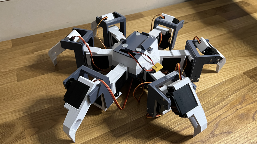
A hexapod robot is a walking robot that uses six legs to move across a surface. The word hexapod refers to a six-legged structure, similar to the body plan of insects such as ants and beetles. Unlike a wheeled robot, which depends on wheels maintaining contact with the ground, a hexapod can coordinate individual legs to lift, reposition, and support its body while moving forward, backward, or turning. When its body and mechanical components are manufactured using a 3D printer, the result is a customizable robot that combines digital fabrication with robotics engineering.
What makes this project particularly appealing is the opportunity to understand how mechanical design, electronics, and software work together. The printed frame provides the robot’s structure, servo motors create movement, and a controller coordinates the motion. By changing the design or adjusting the control code, you can experiment with different walking patterns and improve stability. You do not need to start by designing every component from scratch; the linked project tutorial provides a practical starting point for exploring the build.
2. How Does a Six-Legged Robot Walk?
The secret behind a walking hexapod is coordinated leg movement. Rather than moving all six legs randomly, the robot follows a planned sequence in which some legs lift and move forward while others remain on the ground to support the body. A common approach is the alternating tripod gait, where three legs form one supporting group and the remaining three form another. The groups alternate between supporting the body and moving to their next positions, creating a walking motion that resembles the movement of certain insects.
However, a robot’s actual gait depends on its mechanical configuration, the number of servo motors, and its control software. Some designs use two or three servo-controlled joints per leg, while simpler designs may use fewer joints and provide more limited movement. The number of joints determines how much control the robot has over foot placement, body height, and turning. Understanding these principles helps you appreciate why a six-legged robot is more than a collection of motors: it is a coordinated mechanical system that must balance movement, stability, and power consumption.
3. Understanding Servo Motors and Leg Movement
Servo motors are essential components in many DIY hexapod robots because they allow a controller to command a specific angular position. A typical hobby servo contains a small motor, a gear train, and a feedback mechanism that helps it reach the requested position. When the controller changes the command signal, the servo moves its shaft, allowing a connected leg joint to rotate. By coordinating several servos, the robot can lift its legs, reposition its feet, and change direction.
Choosing suitable servos requires more than looking at their advertised torque. You should consider the robot’s total weight, the length of its leg segments, the number of joints, and the load each motor must support. A longer leg creates greater leverage against the motor, while a heavier printed body increases the force required to lift and stabilize the robot. Power delivery is equally important because multiple servos moving simultaneously can draw substantial current. The exact servo type, quantity, and control method should therefore be confirmed from the original project instructions before buying components.
4. Essential Components Required for the Project
Before starting your build, you need to identify the mechanical parts, electronic components, and tools required by the specific hexapod design. Although many walking robots share similar components, their requirements can differ considerably depending on the number of servo motors, the controller, and the mechanical arrangement. A small educational robot might use lightweight micro servos, while a larger design may require higher-torque servos and a dedicated multi-channel controller. For example, other documented DIY hexapod projects use Arduino boards, PCA9685 servo drivers, 3D-printed structural parts, and separate motor power supplies.
Here is a general component checklist to help you prepare:
| Component | Purpose |
|---|---|
| 3D-printed chassis and legs | Provides the robot’s body and mechanical structure |
| Servo motors | Move the legs and their joints |
| Microcontroller | Executes the walking and movement program |
| Servo driver, if required | Provides additional servo-control channels |
| External power supply or battery | Supplies power to the motors and electronics |
| Screws, nuts, and servo horns | Secure the mechanical assemblies |
| Jumper wires and connectors | Connect the electronic components |
| USB cable and programming computer | Upload firmware and troubleshoot the controller |
You will also need access to a 3D printer or a service that can print the required parts. Basic hand tools, a screwdriver set, and a multimeter can make assembly and testing much easier. Most importantly, check the original Instructables project for the actual component specifications, circuit diagram, and build requirements before ordering anything. This simple step can save you money and prevent the frustration of discovering that your selected servos do not fit the printed brackets.
5. The Role of 3D Printing in Robot Design
One of the biggest advantages of a 3D printed robot is that you can manufacture complex mechanical components without requiring an expensive machining workshop. The body, leg segments, motor mounts, and protective covers can be produced as separate pieces and assembled into a complete structure. If a bracket breaks or a design needs improvement, you can modify the digital model and print a replacement rather than redesigning the entire robot. This makes 3D printing particularly useful for students and makers who want to learn by experimenting.
For a typical hobby project, PLA filament can be a practical starting material because it is easy to print and widely available. However, the correct material depends on the mechanical loads, operating environment, and design geometry. Components that experience repeated bending, impacts, or high loads may benefit from a tougher material or a redesigned structure. Print orientation, wall thickness, infill, and screw-hole tolerances can all affect how well the assembled robot performs. If you use a Bambu Lab, Anycubic, or another FDM printer, inspect each part carefully before assembly and make sure the mounting holes and servo brackets fit without forcing the components into place.
- YouTube making video: https://youtu.be/Jjj-NTkR_kk?si=9sq0gf5YgqgakDpF
- Full project tutorial: https://www.instructables.com/3D-Printed-Hexapod-Robot/
6. Electronics, Wiring, and Circuit Design
The electronic system connects the robot’s controller to its moving parts. In a basic arrangement, the microcontroller sends position commands to the servos, which then rotate to the requested angles. When a design uses more servos than the controller can conveniently operate, a dedicated PWM servo driver can simplify the wiring and provide additional output channels. Some open-source hexapod designs use PCA9685 boards for this purpose, although the right solution depends on the hardware and firmware selected.
Power distribution deserves special attention because servo motors can draw high currents, especially when several joints start moving at the same time or encounter resistance. Do not assume that a microcontroller’s onboard 5 V output can safely power every servo. Instead, follow the project’s specified supply voltage and current requirements, provide a suitable motor power source, and establish a common ground between the controller and servo driver where required by the circuit. Check the polarity of every connection before switching on the system. If the controller repeatedly resets, the servos vibrate unexpectedly, or the power supply voltage drops during movement, investigate the power distribution before changing the software. A well-designed circuit is essential for safe, predictable walking.
7. Programming the Hexapod Robot
Programming transforms the assembled structure into a walking machine. The controller must initialize the servo outputs, establish suitable starting positions, and execute a movement sequence that coordinates all six legs. Depending on the design, the software may use predefined servo angles or calculate joint positions from the desired location of each foot. More advanced implementations use inverse kinematics, which converts a target foot position into the angles required at the corresponding joints. These approaches are found in a range of educational and open-source hexapod projects.
If you are new to robotics programming, start by understanding how the supplied code initializes the servos and defines the robot’s neutral position. Next, identify the functions responsible for standing, walking, turning, and stopping, if those features are supported. Adjust movement speed gradually and test one function at a time rather than changing multiple parameters simultaneously. Incorrect servo offsets can cause legs to point in the wrong direction, while poorly coordinated movements may cause the robot to drag its feet or lose balance. Always begin with the robot securely supported so you can test the servos without placing the full weight of the machine on the legs.
8. Step-by-Step Assembly and Testing
The most effective way to build a hexapod is to divide the work into manageable stages. Start with the printed components and electronics laid out on a clean workbench, then compare each item with the project instructions. Assemble one leg first and confirm that its joints move freely before repeating the process for the remaining legs. This gives you an opportunity to catch mechanical mistakes early, when they are easier to correct.
After assembling the legs, attach them to the chassis and mount the controller and power components in their designated positions. Route the wires carefully so they cannot become trapped between moving joints. Connect the electronics according to the original wiring diagram, then upload the provided program and test the servos individually. Once all joints respond correctly, place the robot on a flat surface and try a slow walking sequence. If one leg moves in the opposite direction from the others, check the servo orientation, channel mapping, and calibration settings before attempting a complete walking cycle.
For the featured build, use the project’s own assembly tutorial as the source of truth for the order of assembly and any model-specific settings. The accompanying YouTube making video is useful for visually understanding how the parts fit together.
9. Gait Control and Movement Experiments
Once the robot can stand reliably, gait control becomes one of the most interesting areas to explore. A gait is the repeating sequence of movements used to move the robot’s legs. The alternating tripod gait is a popular option because it divides the six legs into two groups of three, allowing one group to support the body while the other moves forward. This arrangement can provide static stability when the robot’s centre of gravity remains within the supporting area.
You can experiment with walking speed, stride length, foot-lifting height, and the timing between the leg groups. Increasing the stride length may help the robot cover more ground per cycle, but it can also demand more torque and make movement less reliable. Raising the feet higher may help clear small obstacles, although doing so can increase power consumption. The best settings depend on the robot’s weight, leg geometry, surface friction, and motor capabilities. Record the changes you make and compare their results so you can understand which adjustments improve the movement.
10. Common Problems and Troubleshooting
Even a well-designed DIY robot may need several rounds of adjustment before it walks smoothly. One common issue is a servo that struggles to move under load. This can happen when the motor lacks sufficient torque, the joint binds mechanically, or the power supply cannot deliver the required current. Another problem is uneven walking, where some feet touch the ground too early or the robot leans to one side. Incorrect neutral positions, inconsistent assembly, and mismatched servo offsets are all worth checking.
Loose screws can introduce unwanted movement, while overly tight joints can increase friction and place additional strain on the servos. Inspect the printed parts for cracks around screw holes and motor mounts, especially after repeated walking tests. If the robot resets when several servos move together, verify the supply voltage, wiring, grounding, and current capacity. Make changes one at a time, and keep a record of the original configuration so you can reverse an unsuccessful adjustment. If a motor becomes unusually hot, makes persistent grinding noises, or repeatedly stalls, switch off the power and investigate before continuing.
11. How Much Does a DIY Hexapod Cost?
The cost of building a hexapod robot depends on its size, number of joints, controller, power system, and the amount of 3D printing required. A simple educational design may be relatively affordable, while an 18-servo robot with higher-torque motors and a dedicated servo driver can cost considerably more. You should also account for screws, wiring, connectors, filament, and replacement parts rather than budgeting only for the electronics.
The following table provides a planning framework, not a verified price quotation for the featured design.
| Cost category | What affects the cost? |
|---|---|
| 3D printing | Filament quantity, print time, and material |
| Servo motors | Motor count, torque rating, and quality |
| Controller | Arduino, ESP32, or another compatible board |
| Servo driver | Whether the design needs additional control channels |
| Power system | Battery, regulator, charger, and wiring |
| Mechanical hardware | Screws, nuts, brackets, and connectors |
| Tools and extras | Soldering equipment, multimeter, and spare parts |
Before purchasing components, prepare a bill of materials directly from the project tutorial and compare prices from reputable suppliers. If you already own a 3D printer, soldering tools, and a compatible controller, you may be able to reduce the initial cost significantly. However, avoid choosing undersized servos or an inadequate power supply just to save money. Reliable movement is more valuable than a lower parts bill if the robot cannot operate as intended.
12. Applications of Hexapod Robotics
Hexapod robots are useful educational platforms because they demonstrate several engineering principles in a single machine. Students can explore mechanical design, embedded programming, servo control, electronics, and basic robotics mathematics without needing access to a full industrial laboratory. The same platform can also be used to study how robots move across different surfaces and how leg geometry affects stability.
Beyond education, legged locomotion is relevant to research involving uneven terrain, inspection, and mobile manipulation. Six-legged robots can be designed to maintain support even when individual feet are repositioned, although their real-world capabilities depend on their mechanical design, sensors, control algorithms, and environmental conditions. A small DIY hexapod should not automatically be considered suitable for hazardous environments or professional inspection work. Its greatest value for a hobbyist is the opportunity to experiment with the concepts that underpin more sophisticated robotic systems.
13. Future Upgrades: AI, Sensors, and Wireless Control
After the basic walking function works, you can turn your hexapod into a more capable robotics platform. An ultrasonic or time-of-flight distance sensor can help detect nearby obstacles, while an inertial measurement unit (IMU) can provide information about the robot’s orientation and movement. A Bluetooth or Wi-Fi connection may enable remote commands from a smartphone or computer, provided the controller and firmware support the required interface.
You could also experiment with a camera and computer vision to identify objects, track visual targets, or guide movement. However, these features require additional hardware, software, and integration work; they are not automatically included in the original build. A practical upgrade path is to add one feature at a time, beginning with remote control and basic obstacle detection before exploring more advanced autonomy.
For makers interested in artificial intelligence, a hexapod is an excellent way to learn how perception and motion control can work together. The key is to establish dependable low-level movement first. AI cannot compensate for weak mechanical joints, insufficient motor power, or poorly calibrated servos.
14. Where to Find the Tutorial, Code, and 3D Files
If you want to reproduce the featured robot, begin with the original project resources rather than downloading unrelated files and assuming they are compatible. The tutorial and making video are the two main links provided for this build.

Complete project instructions
Follow the 3D Printed Hexapod Robot tutorial on Instructables for the build information and any linked project files.
Start here for assembly details and the components specified by the creator.

Watch the robot being built
Open the YouTube making video to see the featured project.
Use the video alongside the written instructions to understand the assembly.
Before printing, confirm the scale and compatibility of the supplied files. Check whether the tutorial includes the circuit diagram and source code as downloadable attachments or links to other resources. Do not assume that every required file is bundled into a single download. If a particular file is missing, consult the project creator’s notes or discussion rather than substituting a different design’s firmware without checking the hardware configuration.
For additional inspiration, the PCrnjak 3D-printed Hexapod repository on GitHub documents a separate open-source robot with 3D-printable parts and code resources. It is useful for exploring alternative approaches, but its files and requirements should not be assumed to match the featured Instructables build.
15. Conclusion
A 3D printed hexapod robot is a fantastic DIY engineering project for anyone interested in robotics, Arduino, servo motors, and additive manufacturing. Its six-legged design provides a hands-on introduction to coordinated movement, mechanical construction, and embedded control. From printing the chassis to calibrating the motors and tuning the walking gait, each stage offers an opportunity to learn something practical.
You do not need to create a sophisticated autonomous machine on your first attempt. Begin with the documented design, follow the wiring instructions carefully, and make sure the robot can stand and move reliably before adding extra features. Once the fundamentals work, you can experiment with wireless control, sensors, and computer vision to expand its capabilities.
Ready to build your own walking robot? Watch the making video and check out the complete Instructables tutorial.
Would you build this six-legged robot at home? Share your thoughts, and tell us which upgrade you would try first: Bluetooth control, obstacle avoidance, or AI-powered movement! 🤖
Frequently Asked Questions (FAQs)
16. Can beginners build a 3D printed hexapod robot?
Yes! Beginners can build a hexapod by following a documented project and assembling the mechanical and electronic components step by step. Basic knowledge of electronics, servo motors, and programming is helpful, but you can learn these skills while working on the project. Start by understanding the wiring diagram and testing individual servos before attempting to make the robot walk.
17. What software is needed to program a hexapod robot?
The software depends on the controller and firmware used by the particular design. Arduino-based projects commonly use the Arduino IDE and C/C++ code, while other robots may use Python or different embedded development tools. Check the original project’s instructions for the required libraries, board configuration, and source code before installing software.
18. Can I control a hexapod robot using my smartphone?
Yes, provided you add compatible wireless hardware and supporting firmware. Bluetooth and Wi-Fi are common options for sending movement commands from a smartphone. However, smartphone control is an optional feature unless the original design specifically includes it.
19. Are the 3D printable files and source code free?
Check the original Instructables project to see which files and code are provided and whether any usage conditions apply. Availability and licensing can vary between projects. If you intend to modify or redistribute the design, review the creator’s licence and attribution requirements.
20. Can I add artificial intelligence to a DIY hexapod robot?
Yes. You can extend a compatible hexapod with a camera, sensors, wireless communication, or a companion computer to explore computer vision and autonomous navigation. The original movement system should be reliable before you introduce advanced features. Start with simple tasks, such as detecting an obstacle and stopping, then gradually experiment with more complex behaviours.