Robotics has never been more accessible. Whether you are a computer science student, a maker tinkering in your garage, or a STEM educator looking for the ultimate hands-on project, building a robot dog is a rite of passage.
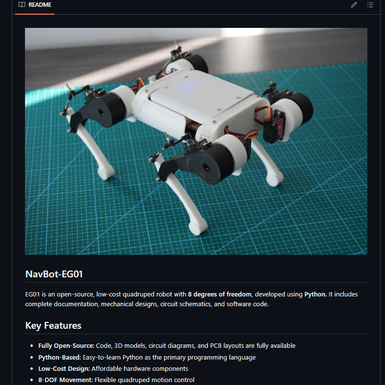
Meet the NavBot-EG01—an open-source, 8-DOF (Degrees of Freedom) desktop quadruped robot designed specifically for learning the fundamentals of robotics, gait generation, and embedded systems without breaking the bank.
In this comprehensive guide, we’ll explore what makes the NavBot-EG01 a fantastic DIY project, what you’ll learn, and how you can build, program, and calibrate your very own robotic companion from scratch.
What is the NavBot-EG01?
Created by robotics developer and researcher Frank Fu, the NavBot-EG01 is a low-cost, 4-legged educational robot powered by an ESP32 microcontroller. Unlike high-end industrial quadrupeds that cost thousands of dollars, the EG01 is tailored for accessibility:
- Fully Open-Source: All 3D print files, circuit schematics, and source code are freely available.
- 8-DOF Architecture: Utilizes 8 servo motors to control leg movement and posture, providing stable walking mechanics.
- Web-Based Control Panel: Connects via Wi-Fi to a local interface where you can calibrate motors and trigger movement commands directly from your browser.
What Will You Learn By Building It?
Building the NavBot-EG01 is more than just an afternoon craft project; it’s a multidisciplinary engineering experience. Here are the core pillars of learning involved:
- Robot Walking Mechanics & Kinematics: Understand how quadrupeds maintain balance and distribute weight across multiple contact points.
- Gait Generation: Learn how to sequence leg movements (such as trotting or walking gaits) to achieve smooth forward and turning motion.
- Embedded Systems & Microcontrollers: Gain hands-on experience wiring and programming with the ESP32 motherboard.
- Hardware Assembly & Prototyping: Master mechanical assembly, servo motor calibration, and power management using voltage regulators and standard hobbyist tools.
What You Need to Get Started
Before diving into assembly, make sure you have the essential components and tools ready:
- Core Electronics:
- ESP32 microcontroller board
- Servo motor driver
- 8x Servo motors (for the 8-DOF joints)
- Power button, voltage regulators, and rechargeable battery pack
- Hardware & Mechanical Parts:
- 3D printed body and leg components (files available on GitHub)
- Standard metric screws, nuts, and miniature bearings
- Type-C USB cable for programming
- Tools:
- Hex key/screwdriver set
- Cross-head screwdriver
- Soldering iron (if custom wiring your motherboard)
- Pliers or wire strippers
Step-by-Step Overview of the Build Process
1. Mechanical Assembly
The assembly begins with the individual legs and joints. You will mount the servo motors into the 3D-printed hip and knee brackets, ensuring that the alignment allows for free, unconstrained movement. Once the four legs are assembled, they are integrated into the main chassis housing the ESP32 motherboard and power distribution system.
2. Wiring & Electronics
The motherboard brings all the electronic components together. Servo motors are wired into the designated driver channels, and the power circuit is connected to the master power switch and battery. (Tip: Keep your wiring organized with zip ties to prevent loose cables from interfering with moving joints!)
3. Software Deployment & Programming
Once hardware assembly is complete, it’s time to bring the robot to life:
- Download the source code repository from the official GitHub link.
- Connect your computer to the ESP32 board via a Type-C USB cable.
- Run the deployment script to flash the control software and upload the built-in HTML interface files to the microcontroller.
4. Calibration & Testing
After flashing the firmware, disconnect the USB cable and power on the robot. The EG01 will broadcast its own local Wi-Fi network (named EG01).
- Connect your computer or phone to the robot’s Wi-Fi.
- Navigate to the robot’s local IP address in your web browser.
- Open the Calibration Panel to fine-tune each servo motor angle (aiming for a neutral 90-degree vertical stance).
- Test basic movement commands like turning left, moving forward, and stopping!
Resources & Links
Ready to start your robotics journey? Check out the official project links to download the 3D print files, source code, and wiring diagrams:
- Watch the Build & Test Video: NavBot-EG01 YouTube Video
- Get the Code & 3D Files: Official GitHub Repository – NavBot-EG01