Connecting Two MPU6050 Sensors to Arduino

In this tutorial, we will learn how to connect two MPU6050 sensors to an Arduino Leonardo. The MPU6050 is a 3-axis gyroscope and 3-axis accelerometer, and it communicates via the I2C bus. Typically, the MPU6050 can have two different I2C addresses: 0x68 and 0x69. By default, the address is 0x68 when the VCC pin is connected to 5V. However, it can be changed to 0x69 by connecting the AD0 pin to 5V instead of the VCC pin.
Components Needed
- Arduino Board
- Two MPU6050 3-axis Accelerometer and Gyro Sensors
- Jumper wires
- Breadboard (optional)
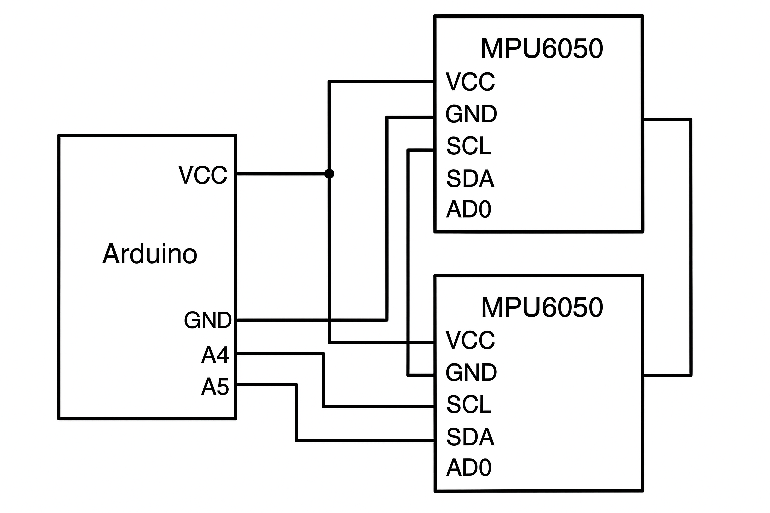
Wiring Diagram
Here’s how to wire the components:
- First MPU6050 (Address 0x68):
- VCC – 5V
- GND – GND
- SCL – A5
- SDA – A4
- AD0 – GND (keeps the default address 0x68)
- Second MPU6050 (Address 0x69):
- VCC -> VCC
- GND -> GND
- SCL -> SCL
- SDA -> SDA
- AD0 -> 5V (changes the address to 0x69)
Both sensors will share the SCL and SDA lines, allowing them to communicate over the I2C bus.
Code Example
The following Arduino code reads data from both MPU6050 sensors and prints it to the Serial Monitor.
#include<Wire.h>
const int MPU2=0x69,MPU1=0x68;
int16_t AcX1,AcY1,AcZ1,Tmp1,GyX1,GyY1,GyZ1;
int16_t AcX2,AcY2,AcZ2,Tmp2,GyX2,GyY2,GyZ2;


 void setup(){
      Wire.begin();
      Wire.beginTransmission(MPU1);
      Wire.write(0x6B);// PWR_MGMT_1 register
      Wire.write(0); // set to zero (wakes up the MPU-6050)
      Wire.endTransmission(true);Wire.begin();
      Wire.beginTransmission(MPU2);
      Wire.write(0x6B);// PWR_MGMT_1 register
      Wire.write(0); // set to zero (wakes up the MPU-6050)
      Wire.endTransmission(true);
      Serial.begin(9600);
     }

 void loop(){

      //get values for first mpu having address of 0x68
      GetMpuValue1(MPU1);
      Serial.print("  ");
      Serial.print("|||");

      //get values for second mpu having address of 0x69
      GetMpuValue2(MPU2);
      Serial.println("");
    }

 void GetMpuValue1(const int MPU){

      Wire.beginTransmission(MPU);
      Wire.write(0x3B); // starting with register 0x3B (ACCEL_XOUT_H)
      Wire.endTransmission(false);
      Wire.requestFrom(MPU, 14, true); // request a total of 14 registers
      AcX1=Wire.read()<<8| Wire.read(); // 0x3B (ACCEL_XOUT_H) & 0x3C (ACCEL_XOUT_L)
      AcY1=Wire.read()<<8|  Wire.read(); // 0x3D (ACCEL_YOUT_H) & 0x3E (ACCEL_YOUT_L)
      AcZ1=Wire.read()<<8| Wire.read(); // 0x3F (ACCEL_ZOUT_H) & 0x40 (ACCEL_ZOUT_L)
      Tmp1=Wire.read()<<8| Wire.read(); // 0x41 (TEMP_OUT_H) & 0x42 (TEMP_OUT_L)
      GyX1=Wire.read()<<8| Wire.read(); // 0x43 (GYRO_XOUT_H) & 0x44 (GYRO_XOUT_L)
      GyY1=Wire.read()<<8| Wire.read(); // 0x45 (GYRO_YOUT_H) & 0x46 (GYRO_YOUT_L)
      GyZ1=Wire.read()<<8| Wire.read(); // 0x47 (GYRO_ZOUT_H) & 0x48 (GYRO_ZOUT_L)
      Serial.print("AcX = ");
      Serial.print(AcX1);
      Serial.print(" | AcY = ");
      Serial.print(AcY1);
      Serial.print(" | AcZ = ");
      Serial.print(AcZ1);
      Serial.print(" | GyX = ");
      Serial.print(GyX1);
      Serial.print(" | GyY = ");
      Serial.print(GyY1);
      Serial.print(" | GyZ = ");
      Serial.println(GyZ1);
     }


 void GetMpuValue2(const int MPU){

      Wire.beginTransmission(MPU);
      Wire.write(0x3B); // starting with register 0x3B (ACCEL_XOUT_H)
      Wire.endTransmission(false);
      Wire.requestFrom(MPU, 14, true); // request a total of 14 registers
      AcX2=Wire.read()<<8| Wire.read(); // 0x3B (ACCEL_XOUT_H) & 0x3C (ACCEL_XOUT_L)
      AcY2=Wire.read()<<8|  Wire.read(); // 0x3D (ACCEL_YOUT_H) & 0x3E (ACCEL_YOUT_L)
      AcZ2=Wire.read()<<8| Wire.read(); // 0x3F (ACCEL_ZOUT_H) & 0x40 (ACCEL_ZOUT_L)
      Tmp2=Wire.read()<<8| Wire.read(); // 0x41 (TEMP_OUT_H) & 0x42 (TEMP_OUT_L)
      GyX2=Wire.read()<<8| Wire.read(); // 0x43 (GYRO_XOUT_H) & 0x44 (GYRO_XOUT_L)
      GyY2=Wire.read()<<8| Wire.read(); // 0x45 (GYRO_YOUT_H) & 0x46 (GYRO_YOUT_L)
      GyZ2=Wire.read()<<8| Wire.read(); // 0x47 (GYRO_ZOUT_H) & 0x48 (GYRO_ZOUT_L)
      Serial.print("AcX = ");
      Serial.print(AcX2);
      Serial.print(" | AcY = ");
      Serial.print(AcY2);
      Serial.print(" | AcZ = ");
      Serial.print(AcZ2);
      Serial.print(" | GyX = ");
      Serial.print(GyX2);
      Serial.print(" | GyY = ");
      Serial.print(GyY2);
      Serial.print(" | GyZ = ");
      Serial.println(GyZ2);
     }
Code Explanation
Libraries and Constants
#include <Wire.h>

const int MPU2 = 0x69, MPU1 = 0x68;
int16_t AcX1, AcY1, AcZ1, Tmp1, GyX1, GyY1, GyZ1;
int16_t AcX2, AcY2, AcZ2, Tmp2, GyX2, GyY2, GyZ2;
The code includes the Wire library, which is used for I2C communication.Constants MPU1 and MPU2 are defined with addresses 0x68 and 0x69, respectively, representing the two MPU6050 sensors.Variables AcX1, AcY1, AcZ1, Tmp1, GyX1, GyY1, GyZ1 store accelerometer, temperature, and gyroscope data for the first MPU6050 sensor.Similarly, AcX2, AcY2, AcZ2, Tmp2, GyX2, GyY2, GyZ2 store the same data for the second MPU6050 sensor.
Setup Function
void setup() {
    Wire.begin();
    Wire.beginTransmission(MPU1);
    Wire.write(0x6B); // PWR_MGMT_1 register
    Wire.write(0); // set to zero (wakes up the MPU-6050)
    Wire.endTransmission(true);

    Wire.begin();
    Wire.beginTransmission(MPU2);
    Wire.write(0x6B); // PWR_MGMT_1 register
    Wire.write(0); // set to zero (wakes up the MPU-6050)
    Wire.endTransmission(true);

    Serial.begin(9600);
}
- The
setupfunction initializes the I2C communication with both MPU6050 sensors. Wire.begin()initializes the I2C bus.- For
MPU1andMPU2, the code wakes up the sensors by writing to thePWR_MGMT_1register (address0x6B) and setting it to0. - Finally,
Serial.begin(9600)starts the serial communication at 9600 baud rate.
Loop Function
void loop() {
    // get values for the first MPU with address 0x68
    GetMpuValue1(MPU1);
    Serial.print("  ");
    Serial.print("|||");

    // get values for second MPU with address 0x69
    GetMpuValue2(MPU2);
    Serial.println("");
}
- The
loopfunction continuously retrieves and prints data from both MPU6050 sensors. - It calls
GetMpuValue1for the first sensor andGetMpuValue2for the second sensor. - The
Serial.printandSerial.printlnfunctions are used to format the output for readability.
User-Defined Functions
GetMpuValue1 Function
void GetMpuValue1(const int MPU) {
    Wire.beginTransmission(MPU);
    Wire.write(0x3B); // starting with register 0x3B (ACCEL_XOUT_H)
    Wire.endTransmission(false);
    Wire.requestFrom(MPU, 14, true); // request a total of 14 registers

    AcX1 = Wire.read() << 8 | Wire.read(); // 0x3B (ACCEL_XOUT_H) & 0x3C (ACCEL_XOUT_L)
    AcY1 = Wire.read() << 8 | Wire.read(); // 0x3D (ACCEL_YOUT_H) & 0x3E (ACCEL_YOUT_L)
    AcZ1 = Wire.read() << 8 | Wire.read(); // 0x3F (ACCEL_ZOUT_H) & 0x40 (ACCEL_ZOUT_L)
    Tmp1 = Wire.read() << 8 | Wire.read(); // 0x41 (TEMP_OUT_H) & 0x42 (TEMP_OUT_L)
    GyX1 = Wire.read() << 8 | Wire.read(); // 0x43 (GYRO_XOUT_H) & 0x44 (GYRO_XOUT_L)
    GyY1 = Wire.read() << 8 | Wire.read(); // 0x45 (GYRO_YOUT_H) & 0x46 (GYRO_YOUT_L)
    GyZ1 = Wire.read() << 8 | Wire.read(); // 0x47 (GYRO_ZOUT_H) & 0x48 (GYRO_ZOUT_L)

    Serial.print("AcX = ");
    Serial.print(AcX1);
    Serial.print(" | AcY = ");
    Serial.print(AcY1);
    Serial.print(" | AcZ = ");
    Serial.print(AcZ1);
    Serial.print(" | GyX = ");
    Serial.print(GyX1);
    Serial.print(" | GyY = ");
    Serial.print(GyY1);
    Serial.print(" | GyZ = ");
    Serial.println(GyZ1);
}
- This function reads data from the first MPU6050 sensor.
- It starts communication with the sensor and requests 14 bytes of data starting from register
0x3B. - The accelerometer, temperature, and gyroscope data are read and stored in respective variables.
- The data is then printed to the Serial Monitor.
GetMpuValue2 Function
void GetMpuValue2(const int MPU) {
    Wire.beginTransmission(MPU);
    Wire.write(0x3B); // starting with register 0x3B (ACCEL_XOUT_H)
    Wire.endTransmission(false);
    Wire.requestFrom(MPU, 14, true); // request a total of 14 registers

    AcX2 = Wire.read() << 8 | Wire.read(); // 0x3B (ACCEL_XOUT_H) & 0x3C (ACCEL_XOUT_L)
    AcY2 = Wire.read() << 8 | Wire.read(); // 0x3D (ACCEL_YOUT_H) & 0x3E (ACCEL_YOUT_L)
    AcZ2 = Wire.read() << 8 | Wire.read(); // 0x3F (ACCEL_ZOUT_H) & 0x40 (ACCEL_ZOUT_L)
    Tmp2 = Wire.read() << 8 | Wire.read(); // 0x41 (TEMP_OUT_H) & 0x42 (TEMP_OUT_L)
    GyX2 = Wire.read() << 8 | Wire.read(); // 0x43 (GYRO_XOUT_H) & 0x44 (GYRO_XOUT_L)
    GyY2 = Wire.read() << 8 | Wire.read(); // 0x45 (GYRO_YOUT_H) & 0x46 (GYRO_YOUT_L)
    GyZ2 = Wire.read() << 8 | Wire.read(); // 0x47 (GYRO_ZOUT_H) & 0x48 (GYRO_ZOUT_L)

    Serial.print("AcX = ");
    Serial.print(AcX2);
    Serial.print(" | AcY = ");
    Serial.print(AcY2);
    Serial.print(" | AcZ = ");
    Serial.print(AcZ2);
    Serial.print(" | GyX = ");
    Serial.print(GyX2);
    Serial.print(" | GyY = ");
    Serial.print(GyY2);
    Serial.print(" | GyZ = ");
    Serial.println(GyZ2);
}
GetMpuValue2 Function
- This function is similar to
GetMpuValue1, but it reads data from the second MPU6050 sensor.
- The code initializes two MPU6050 sensors and reads data from them.
- Each sensor is configured with a unique I2C address (
0x68and0x69). - The
setupfunction initializes the sensors and starts serial communication. - The
loopfunction continuously retrieves data from both sensors and prints it to the Serial Monitor. - User-defined functions
GetMpuValue1andGetMpuValue2handle reading and printing data from each sensor respectively.
This setup allows for simultaneous data acquisition from two MPU6050 sensors connected to an Arduino.